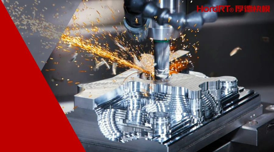
A machining center running at a high spindle speed is not automatically performing high-speed machining. The real distinction lies in how spindle rotation, feed motion, tool engagement, acceleration, and toolpath geometry work together. For engineers and purchasing teams, understanding that distinction matters because simply increasing RPM can create heat, vibration, or tool wear without delivering a shorter or more stable cycle.
High speed CNC machining is better understood as a coordinated machining strategy. The objective is to maintain productive cutting motion while controlling the forces and thermal conditions generated by material removal. Haas documentation, for example, describes high-speed machining in terms of faster feedrates, complex toolpaths, look-ahead, and controlled motion rather than spindle speed alone.
What Makes CNC Machining “High Speed”?
Conventional thinking often associates machining speed with spindle RPM. RPM is certainly part of the equation, but cutting speed also depends on tool diameter. Haas’s machining reference gives the relationship between cutting speed, tool diameter, and spindle speed, while feed rate depends on feed per tooth, spindle speed, and the number of cutting teeth.
That distinction becomes important when selecting parameters for a real part. A small-diameter cutter may require substantially higher RPM to achieve an appropriate cutting speed than a larger tool. Raising spindle speed without considering cutter diameter, feed per tooth, material, and tool engagement can therefore produce an unbalanced process.
High-speed machining also relies on the machine control’s ability to anticipate upcoming motion. Look-ahead allows the control to evaluate successive blocks of programmed movement and manage acceleration and deceleration more effectively. Modern HSM implementations can therefore maintain higher feedrates through suitable toolpaths while slowing where geometry or accuracy requires it.
Why Toolpath Control Matters More Than RPM Alone
Complex 3D surfaces reveal why toolpath strategy is central to high-speed machining. A cutter may be programmed with an impressive feedrate, yet the machine cannot necessarily maintain that value through every corner, direction change, or short segment.
Sharp changes in direction require the machine to reduce motion if it is to preserve the programmed geometry. Haas specifically notes that smoothly blended shapes are better suited to high-speed machining, whereas sharp corners can force feedrate reductions or create corner-rounding effects.
CAM programming therefore becomes part of the manufacturing strategy. Excessively short blocks can create a large stream of motion commands, while insufficiently detailed toolpaths may produce faceting or force slower motion around larger angular transitions. The objective is not simply to generate more toolpath points, but to produce a smooth path that the machine control can execute efficiently.
HordRT approaches rapid CNC production by treating programmed geometry and machining execution as linked decisions. In practice, this can involve reviewing CAM output for segment length, data-point density, corner blending, and feedrate continuity, then checking those choices against the machine control’s look-ahead, acceleration, and contouring behavior. The aim is to reduce the risk of toolpaths that appear acceptable in CAM but are difficult for the machine to execute smoothly. Its published CNC machining information identifies speed, precision, thermal management, vibration control, and material-specific parameter selection as connected process issues rather than isolated variables.
How Cutting Parameters Shape the Result
Cutting parameters determine whether a high-speed strategy actually removes material efficiently. Cutting speed, spindle speed, feed rate, feed per tooth, axial depth of cut, and radial depth of cut interact continuously during milling.
Material removal rate provides a useful way to view the relationship. Haas defines milling MRR using axial depth of cut, radial depth of cut, and feed rate. Increasing one parameter does not automatically make the process more productive if another variable creates excessive cutting load or instability.
Tool diameter and flute count also influence feed calculations. A multi-flute cutter operating at a given RPM can use a different feedrate from a cutter with fewer flutes while maintaining the same feed per tooth. Tool selection consequently has to match the material, geometry, machine capability, and intended cutting conditions.
Thermal management deserves equal attention. HordRT’s technical discussion identifies heat as a factor that can accelerate tool wear and affect the machined material, making cooling and appropriate cutting tools part of the process design.
Where High-Speed Strategies Create the Most Value
High-speed machining is particularly relevant when a component contains complex contours, sculpted surfaces, or many closely spaced toolpath movements. Mold and die work is a common example because smoothly contoured geometry can require extensive continuous motion. Haas describes high-speed machining as especially useful for smoothly sculpted shapes typical of mold making.
The strategy can also be valuable when cycle time is influenced heavily by contouring rather than simple straight-line cuts. Four- and five-axis programs are another area where controlled high-speed motion can support complex geometry; Haas specifically recommends HSM for 3D and simultaneous four- or five-axis programs.
That does not mean every component should be machined at maximum available speed. A relatively simple part with long linear cuts may gain little from an advanced high-speed strategy if its existing machining path already permits efficient feed motion.
How Manufacturers Avoid Turning Speed Into a Problem
Higher cutting intensity can expose weaknesses in machine rigidity, workholding, tooling, programming, or cooling. Vibration is particularly troublesome because it can damage surface quality, accelerate tool wear, and make dimensional results less predictable.
Process stability therefore comes before headline RPM. Tool selection must suit the material and cutting conditions, while the workholding arrangement must resist the forces generated during cutting. Machine controls also need appropriate acceleration and contouring behavior to prevent aggressive changes in motion.
Programming quality is equally significant. Haas documentation warns that unsuitable stroke lengths and data-point densities can interfere with smooth high-speed execution.
HordRT‘s published manufacturing guidance similarly treats heat, vibration, material response, tooling, and cooling as variables that require process-specific adjustment rather than one universal parameter set.
Choosing the Right Machining Strategy for a Part
The practical question is not whether a machine can run fast, but whether the part’s geometry and production objectives justify a high-speed strategy. Engineers should first examine the dominant toolpaths: are they long and uncomplicated, or short, highly contoured, and directionally complex?
Material and cutter selection come next. Cutting speed and feed calculations need to reflect tool diameter, flute count, feed per tooth, and depth of cut rather than relying on a nominal RPM target.
Finally, the machining supplier should evaluate the complete process: CAM output, machine control, workholding, tooling, cooling, inspection requirements, and expected production volume. That assessment is more meaningful than specifying “high speed” as a standalone requirement.
High-speed machining ultimately describes a coordinated way of controlling material removal and machine motion. The strongest results come when spindle speed, feedrate, tool engagement, toolpath geometry, and machine dynamics are designed as one system. For buyers evaluating a CNC supplier, that process-level understanding provides a more useful basis for judging capability than a machine’s maximum RPM alone.