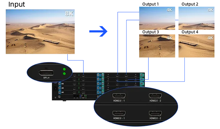
An LED wall has a native raster even when its physical outline resembles no standard video format. A display that is 7,680 pixels wide and 1,080 pixels high cannot be specified accurately as merely “4K” or “ultra-wide.” Selection begins with exact width, height, and source placement, because a video processor for LED wall applications must carry the real canvas without hidden cropping or unnecessary scaling.
Aspect ratio then becomes a relationship between the source and that raster. Black bars, stretched images, and lost edges are usually consequences of an undefined fit rule, not evidence that more resolution alone is needed.
Calculate the Native Raster from the Cabinets
The native LED raster comes from calculations along two axes: cabinet pixel width across the installed columns and cabinet pixel height across the installed rows. The resulting width and height define the output canvas, while their product indicates total pixels. A video processor for LED wall use must fit all three limits because two canvases with the same pixel total can have very different maximum widths.
Every independent surface should be calculated separately before deciding whether outputs are mirrored, spliced, or assigned to different destinations. The drawing should show the exact pixel region owned by each path so that the processor configuration can later be verified against the installed wall.
For example, doubling width while halving height can preserve the same pixel total but exceed a width limit that a conventional 16:9 test never reveals. Cabinet maps also expose partial rows, rotated sections, or separate ribbons that need independent output origins even when the installation appears visually continuous.
Define How Each Source Fits the Aspect Ratio
Sources may fill, fit, crop, or occupy a designed window. Fill can distort geometry when source and wall ratios differ. Fit preserves the full image but may create bars. Crop preserves proportions while discarding edges. A windowed layout avoids both by placing the source inside a deliberate composition.
The video processor for LED wall deployment should apply these rules consistently rather than leaving operators to resize content by eye. Fit, fill, crop, and stretch rules produce different results even when the same source and canvas are used.
The approved rule should be recorded per source class so later operators do not solve an aspect-ratio mismatch by introducing inconsistent geometry. Pixel-to-pixel presentation is preferable for fine text and graphics when source and canvas dimensions permit it.
Where scaling is unavoidable, test patterns with circles, grids, and edge labels reveal distortion and lost content more clearly than ordinary footage. Content production rules can reduce processing ambiguity. Templates built at the native raster or at an agreed proportional master make fit behavior predictable.
Mixed source ratios still need per-window policies, because a camera, presentation deck, and dashboard may each require a different balance between preserved edges and filled space. Safe-area guides can protect titles and controls when a crop is permitted. They turn a visual preference into a measurable production rule that can be checked before content reaches the wall.
Count Sources, Windows, and Peak Formats Separately
Input connectors, active sources, and visible layers are different quantities. A processor may receive many feeds but display only a subset, or it may reuse one feed in several windows. The video processor for LED wall selection therefore needs a scene schedule listing each source format, simultaneous window count, and the highest-resolution combination expected during operation.
An 8K source also affects acquisition capacity even if only part of it is shown. Full RGB 4:4:4 processing protects fine colored detail that can suffer under chroma subsampling, particularly in data-heavy command displays and close-viewed presentation walls.
Match Output Interfaces to the Control Boundary
Standard video outputs suit systems where separate LED controllers already handle sending and cabinet mapping. Direct Ethernet or fiber output suits a design in which processing and LED control share one platform. A video processor for LED wall use cannot be chosen from canvas pixels alone; the required interface and responsibility for the downstream load are equally important.
Within the Kystar portfolio, SEn supports 8K acquisition, processing, and transmission, DP1.4 input up to 8K x 4K, RGB 4:4:4, a range of HDMI, DP, DVI, SDI, IP, and HDBaseT interfaces, and as many as 32 4K@60Hz output channels. SHn integrates video processing with direct LED control and scales from SH2 to SH14, reaching up to 224 Ethernet ports and approximately 147.2 million pixels on the largest model.
Reserve Capacity for Real Operating Scenes
Nominal fit is not the same as stable operation. Transitions, overlapping layers, preview feeds, and future source additions consume capacity beyond a static full-screen test. Headroom should be assigned to named functions rather than an arbitrary percentage.
One spare 4K input, an additional preview route, or two future windows are clearer engineering reserves than a general claim that the system has room to grow. The selected video processor for LED wall operation should run the most demanding approved scene for an extended period, then repeat source changes and preset recalls without altering geometry.
A defensible choice leaves a written chain from cabinet raster to source rules, window count, output paths, and test results. That chain answers both resolution and aspect-ratio questions. It also prevents a familiar mistake: purchasing around a standard video label, then discovering that the wall’s non-standard width, interface, or scene structure falls outside the planned configuration.